The Perfect Airplane Wing
Is it thick or thin, elliptical or squared, straight or cranked? Yes.
:focal(2904x895:2905x896)/https://tf-cmsv2-smithsonianmag-media.s3.amazonaws.com/filer/83/05/83053148-4b8f-4ab6-8a89-c092b5301e70/06v_fm2019_fmhocomposite_live.jpg)
Before the outbreak of World War II, relations between British and German aeronautical engineers were sufficiently cordial for Reginald Mitchell, chief designer of the Supermarine Spitfire, to write to his German counterpart, Ernst Heinkel, congratulating him on his He 70 Blitz. The Blitz (German for lightning), designed in 1932, was a fast five-seat mailplane. One of its noteworthy features was the elliptical planform of its wing; another was the extremely smooth surface finish of its flush-riveted airframe. “We have been unable to achieve such smooth lines in the aircraft that we entered for the Schneider Trophy Races,” Mitchell wrote to Heinkel, and he went on to report that a Blitz that Rolls-Royce had acquired and fitted with their 810-horsepower Kestrel engine was “appreciably faster than our fighters.”
The British fighters of the day were superannuated biplanes, so the comparison cannot have been deeply gratifying to Heinkel. But Mitchell’s generous appreciation of the carefully streamlined He 70 gave legs to a story that the design of the Spitfire was “copied” or “cribbed from” or “influenced by” the Blitz.
Many years later Beverley Shenstone, a Canadian-born aerodynamicist who had had principal responsibility for the design of the Spitfire wing, emphatically denied the charge, pointing out that the elliptical wing shape had been used in other aircraft, and that its advantages were well known.
Indeed, the virtues of elliptical wings had been articulated by British theorist Frederick Lanchester in 1907. The shape had been chosen for the Spitfire “early on,” Shenstone said, because Mitchell, having used thick airfoil sections on a lackluster precursor of the Spitfire, wanted thinner ones for the new fighter. The problem was that the four .303 machine guns per side required by the Royal Air Force would not fit within a thin wing of straight taper. The elliptical wing’s taper began fairly far outboard, and so it enveloped the guns comfortably. “I don’t give a damn whether it’s elliptical or not so long as it covers the guns!” Shenstone reported Mitchell saying.
Still, the success of one design with a conspicuous characteristic could not help influencing others. The purported virtue of the elliptical wing was that, theoretically at least, it would generate the least possible lift-dependent, or induced, drag. Induced drag is the drag incurred by the mere action of generating lift, as opposed to the drag due to skin friction (parasite drag) and to turbulent eddies left behind as the airplane passes. Induced drag increases as the airplane slows down and the angle at which the wing meets the air increases, so it mainly affects rate of climb and high-G maneuvering. Parasite drag, on the other hand, affects top speed. The principle identified by Lanchester is that induced drag is at a minimum when the spanwise distribution of lift is elliptical, and there is an equation to prove it.
The idea was always more theoretical than practical. Real airplanes would have fuselages and engine nacelles and control-surface gaps and underwing radiators and air intakes and guns, all of which made the lift distribution depart from the ideal of a smooth ellipse. The battle for perfection was inevitably lost before it began.
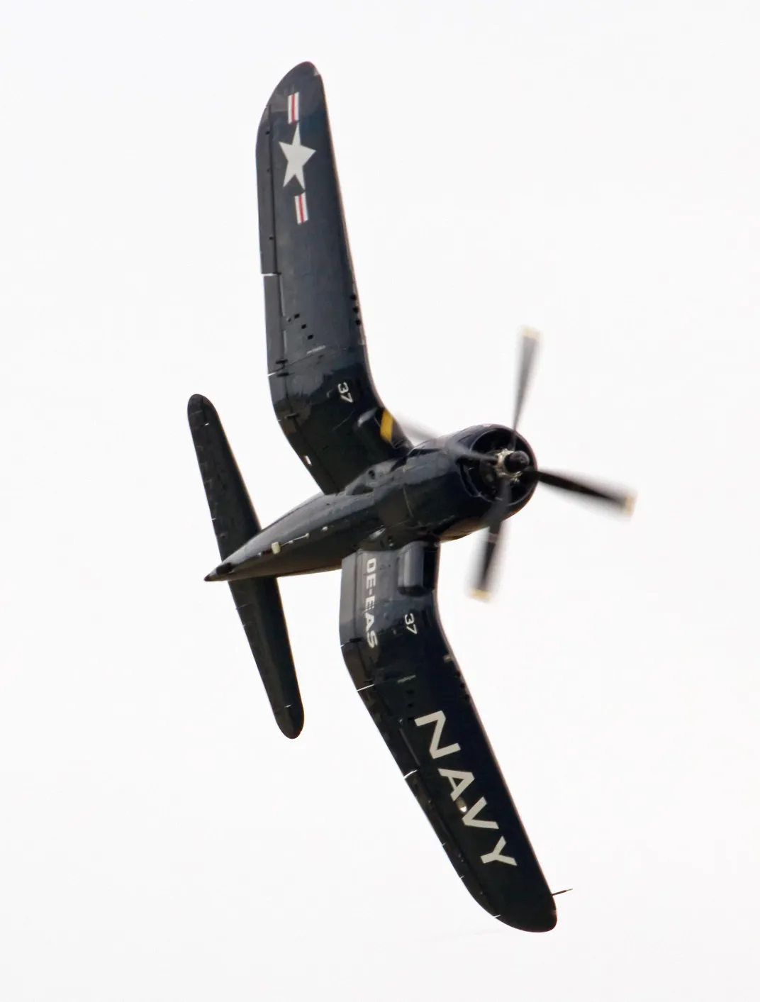
Nevertheless, the spell of the ellipse persisted. The Hawker Sea Fury used an elliptical wing, but somehow didn’t get the love for it that the Spitfire did. Republic Aircraft’s founder Alexander de Seversky and his chief designer, Alexander Kartveli, both favored a wing plan shared by the prewar P-35 and the later P-47 Thunderbolt: a straight leading edge with curved tips and semi-elliptical trailing edge, which gave an elliptical area distribution without the manufacturing difficulties of a curved leading edge.
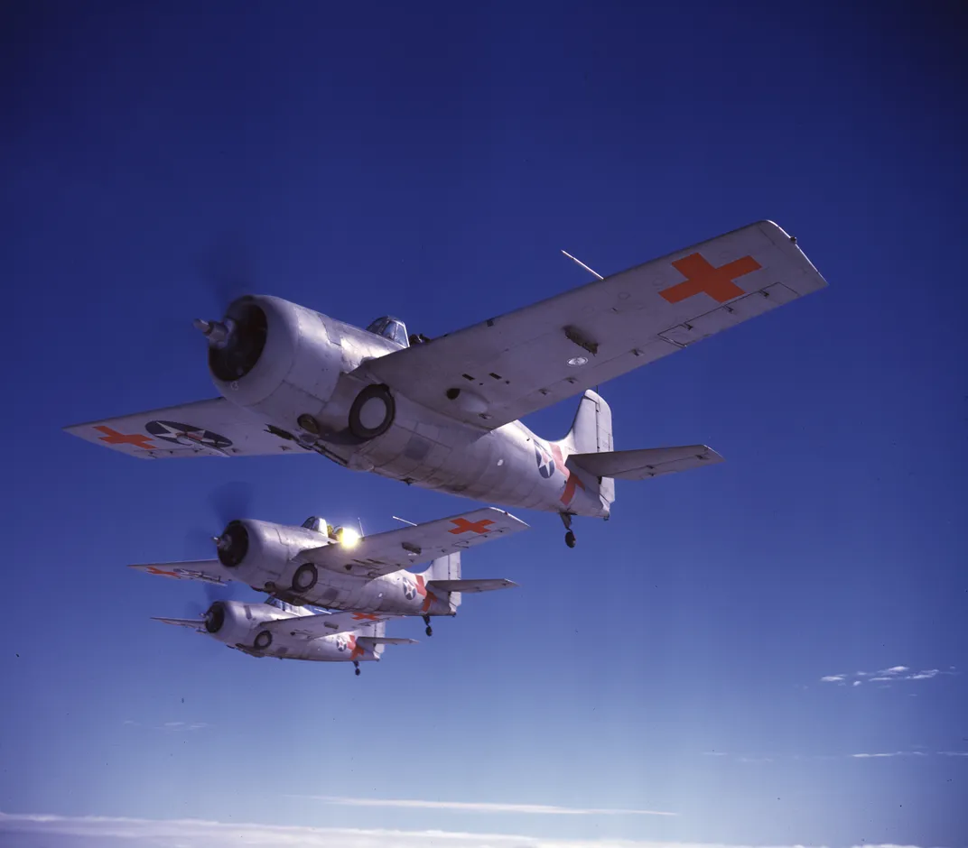
Other firms tried trapezoidal wings, or ones that approximated an ellipse with two or three trapezoidal panels, and found them not noticeably inferior to the elliptical. The rounded wingtip survived as a relic of the ideal ellipse until North American’s P-51 and Grumman’s F6F Hellcat abandoned even it. The Hellcat continued the practice of rounding empennage tips; not so the P-51, whose fin and stabilizer were squared-off as brutally as its wings.
In the end, an “ideal” lift distribution and a rounded tip did not seem to make all that much difference.
What made the game of airplane design difficult and seductive was that links between causes and effects were often obscure. It might be the case that an airplane had a conspicuous feature, like the elliptical wing of the Heinkel, but that its good (or bad) performance was due, in fact, to something else. There was always room in design decisions for hunches, theories sound and crackpot, and a personal sense of style.
To a discerning eye, the differences between the wings on both the Spitfire and He 70 were as striking as the similarities. The He 70’s wing, viewed head-on, has an inverted gull shape, and in top view it grows narrower near the fuselage. Both features were intended to reduce aerodynamic interference between the fuselage and the wing. The Spitfire, however, ignored both refinements and used a voluminous wing-root fairing, a solution that simplified wing construction but might have cost a smidgen of speed or climb rate.
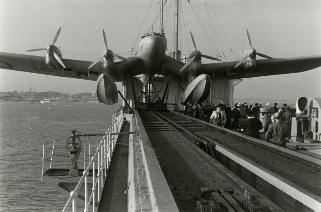
The inverted gull arrangement was a favorite of Richard Vogt, the highly creative chief designer of the German firm of Blohm & Voss. He used it in a dive bomber that resembled a baby Stuka, and in the Ha 139, a four-engine floatplane that flew passenger- and mail-service routes over the South Atlantic before the war. Vogt then tried the opposite arrangement—the upright gull wing—on a three-engine flying boat.
Designers of medium-size flying boats often used the gull wing to position the wing-mounted engines farther from the water. But Vogt carried the idea a little too far. The inboard wing panels of his three-engine Ha 138 formed a steep V, with the middle engine perched on a pylon between them. The aerodynamics of the design proved so unfortunate that he was obliged to replace the gull wing with a straight one, but not before a wag at a British aviation magazine supplied this caption to a picture of the 138:
Richard Vogt, that original man
Turns out aeroplanes uglier than
Most any other designer can.
Here is shown on Baltic Sea
A typical Vogt monstrosity,
The One-Three-Eight by B and V.
Wings with kinks (many had them, if only between a straight center section and outer panels) obscured a basic characteristic of practically all wings, namely dihedral. Dihedral is the slight upward tilt of the wings—or at least of their outer panels. Its purpose is to cause the airplane to return to level flight after a disturbance. The word is usually applied to wings, but “dihedral effect” is really a property of the entire airplane, with the fuselage and tail surfaces also playing important roles and wing sweep having the same effect as upward tilt. Too much dihedral effect is a fault, and swept-wing airplanes consequently tend to have less wing tilt than straight-wing ones do—or none at all.
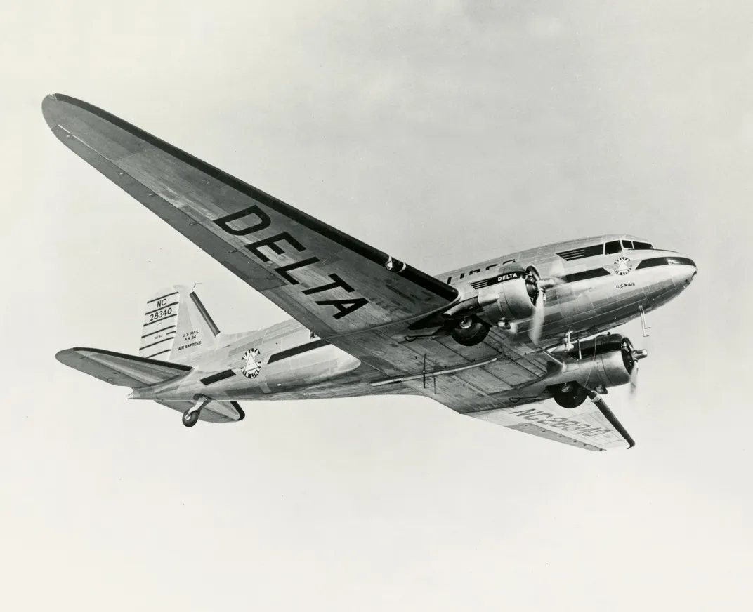
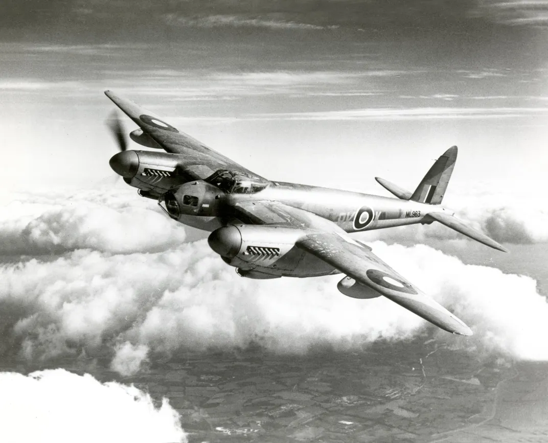
Prominent characteristics of wings often look as though they must have some subtle or profound aerodynamic purpose when they really don’t. One example is moderate sweep. The planforms of wings from 1930 to 1945 show a great deal of variety, from straight leading edges and swept-forward trailing edges (de Havilland Mosquito) to the opposite (Douglas DC-3, North American T-6). The taste of designers, structural arrangements within the wing, and, occasionally, the need to adjust for an errant center-of-gravity location account for most decisions about sweep. None of the airplanes of the period was fast enough to benefit from genuinely swept wings as we know them today.
On the other hand, one of the things that mattered most about a wing was something quite obvious: how short and broad or long and narrow it was.
The ratio of the length of a wing to its breadth is known as aspect ratio. It was understood even in the 19th century, from observations of birds, that wings of larger span and higher aspect ratio could carry a load with less effort (because their induced drag is less). On the other hand, such wings on airplanes, as opposed to birds, are less maneuverable in flight and more difficult to make strong and stiff than short, broad ones of lower aspect ratio.
The wings of subsonic airplanes consequently fell into two broad categories. Wings intended for fast, maneuverable, highly-stressed aircraft like fighters tended to be thin and to have an aspect ratio of five or six. Those designed for transports—bombers, cargo haulers, and airliners—used higher aspect ratios, often 10 or more, and, in order to accommodate the necessary internal structure, they were thick in profile.
Although many biplane wings had been simple rectangles, monoplane wings were almost always tapered. The reason was structural. Biplane wings together formed a bridge-like truss that distributed stresses evenly across the span. Unbraced cantilever monoplane wings, on the other hand, experienced extremely large stresses where the wing met the fuselage. In order to cope with them, it was desirable both to make the root thicker than the tip and also to reduce the amount of lift being produced far outboard. Monoplane wings were therefore almost always tapered in both width and thickness.
Taper ratio—the ratio of the width, or chord, of a wing at its tip to that at its root—seems initially to have been a matter of taste. Before and during World War II, taper ratios of .25 or less were common: The tip might be a quarter as wide as the root. Junkers tapered the wings of the 88 series of high-altitude bombers almost to a point. The attraction of extreme taper was that it allowed increasing the wingspan—which improved climb rate and high-altitude performance while reducing cruising fuel consumption—without adding much structural weight or drag-producing surface area. The disadvantage was that airplanes with highly tapered wings were prone to roll violently when stalled. Wings could be twisted a few degrees to delay tip stall, but twist increased drag. Toward the end of World War II, extreme taper ratios were on the way out: Tip chords of a third to a half of the root chord became standard.
Though many of the basic characteristics of wings were arrived at by trial and error, pure research was not lacking. The major skyfaring nations all had government-sponsored aeronautical research establishments: England’s Farnborough, France’s Meudon, Russia’s Kuchino, and in the United States, the National Advisory Committee for Aeronautics, launched by Congress in 1915 and based at Hampton, Virginia. From their wind tunnels came many of the fundamental discoveries that shaped airplanes.
An inconspicuous but important feature of every wing was its profile, or airfoil section. National centers for aeronautical research in France, Germany, England, and the United States had compiled families of airfoils adapted to airplanes of various speeds and wing loadings. Most of these airfoils had been created using abstract mathematical procedures that were not related to the physics of fluid flows, but simply yielded smooth shapes that happened to be rounded at one end and pointed at the other. The aerodynamic characteristics of those shapes were then measured by wind tunnel testing, and designers would pick out suitable ones from catalogs.
Much of the seminal work on airfoil theory was due to German scientist Max Munk, who had been brought into NACA’s Langley laboratory as a technical advisor in 1920 and eventually became chief of aerodynamics. Munk, whom an official history describes as “simultaneously an aerodynamical wizard and an unstable charlatan,” proved to be a difficult person to work with or under. He was dictatorial, rigid, obsessed with hierarchy, insensitive to people, and, because of an incomplete command of English, sometimes incomprehensible. Langley’s engineers circulated ludicrous fables about how Munk, who learned to drive after coming to the United States, calibrated his turns by means of a protractor-like device affixed to his steering wheel. In 1927, after the Langley section heads signaled their displeasure with him by resigning en masse, Munk was removed from his position.
The departure of Munk has been seen as the moment when control of NACA’s agenda passed from scientists to engineers. Henceforth, research efforts were principally directed to practical problems, often proposed in round tables with manufacturers. This emphasis on technology rather than science paid off in many ways, but it may also have accounted for the fact, revealed after the end of the war, that Germany was ahead of the Allies in pure aeronautical science.
Nevertheless, pure science was not dead at NACA, and at times the Americans surpassed the Germans. In the late 1930s, NACA aerodynamicist Eastman Jacobs developed a system for designing airfoils to yield a set of desired characteristics. Its first great success was the so-called “laminar flow” airfoil used on the P-51 Mustang.
In theory, keeping the flow of air over a wing laminar, that is, smooth and free of even very small-scale turbulence, could halve the drag. In practice, like the elliptical planform, laminar profiles did not deliver all that they promised because manufactured wings never had the surface smoothness that laminar flow required. It remained a matter of personal pride and endless argument among the men who had worked on the Mustang whether the laminar flow wing or the so-called “Meredith effect” cooling system was more responsible for its speediness. They all died before settling the question.
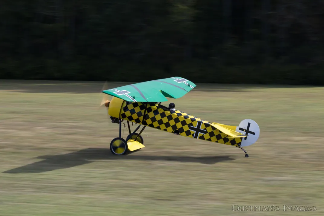
The basic characteristics of modern subsonic wings—including those of all the airplanes of World War II—appeared early in aviation history. The wood wing of the Fokker D.VIII of 1918 was of moderate taper, with an aspect ratio of six, a relatively thick airfoil section, recessed ailerons, and a cantilever structure free of external bracing. Although it was much closer in time to the Wright brothers than to World War II, it was so advanced it would have looked perfectly at home on a 1940s fighter.
The failure of manufacturers and military services to appreciate the Fokker wing and to embrace the monoplane immediately after World War I exposes a persistent strain of conservatism and timidity in airplane design. Because there was so much uncertainty about which ideas were good and which ones bad, manufacturers fell back, again and again, upon the tried and proven.
In practical airplanes, everything influences everything else, accurate testing and documentation are difficult, and the effects of small incremental changes are frequently too subtle to measure. Sometimes two seemingly beneficial modifications cancel one another. The natural camaraderie and mobility of workers in the field tend to diffuse detailed engineering information; at the same time, the subtleties of conceptual design tend to evaporate through human mortality and institutional forgetfulness. Rumor, misunderstood ideals, and premature optimism probably had as much effect on aeronautical progress as hard science did.
The variety of airplane shapes offers a lesson. It is better to view the history of airplane forms as a Darwinian process, with successful designs eventually displacing less successful ones in a process full of backtracks and false starts, than as the systematic pursuit of a scientific ideal. From this perspective, the interesting question is not whether the design of a certain Heinkel airplane influenced that of a certain Supermarine one, but why, if the elliptical shape is so great, so few airplanes have ever used it.
Unfortunately, most designers of airplanes did not leave behind detailed accounts of how they made their choices and which ones they later regretted or congratulated themselves upon. For that matter, different people working on the same airplane may give conflicting accounts of the reasons for its features. As a result, we are often reduced to guessing why wings—and entire airplanes—are shaped the way they are.
Every airplane is a collision between the ideal and the practical. Arrayed against the ideal have been the recalcitrance of construction materials; the need to accommodate passengers and cargo; the requirement of landing gear; and the messy and awkward need for propulsion, with its attendant demands for ground clearance, cooling, serviceability, and so on. The challenge for manufacturers was to marry the ideal shapes of the laboratory to the practical requirements of transport and battle. The mark of a great aeronautical designer has always been an ability, not to carry one characteristic to an extreme, but to combine a number of conflicting elements into a successful whole. There was never just one solution to the puzzle: If there had been, there would have been, in the end, just one perfect airplane.
Subscribe to Air & Space Magazine Now
This story is a selection from the February/March issue of Air & Space magazine